5-DOF Robotic Arm
A servo-driven arm with five rotational axes and a parallel-jaw gripper, built around a hand-derived inverse kinematics solution.
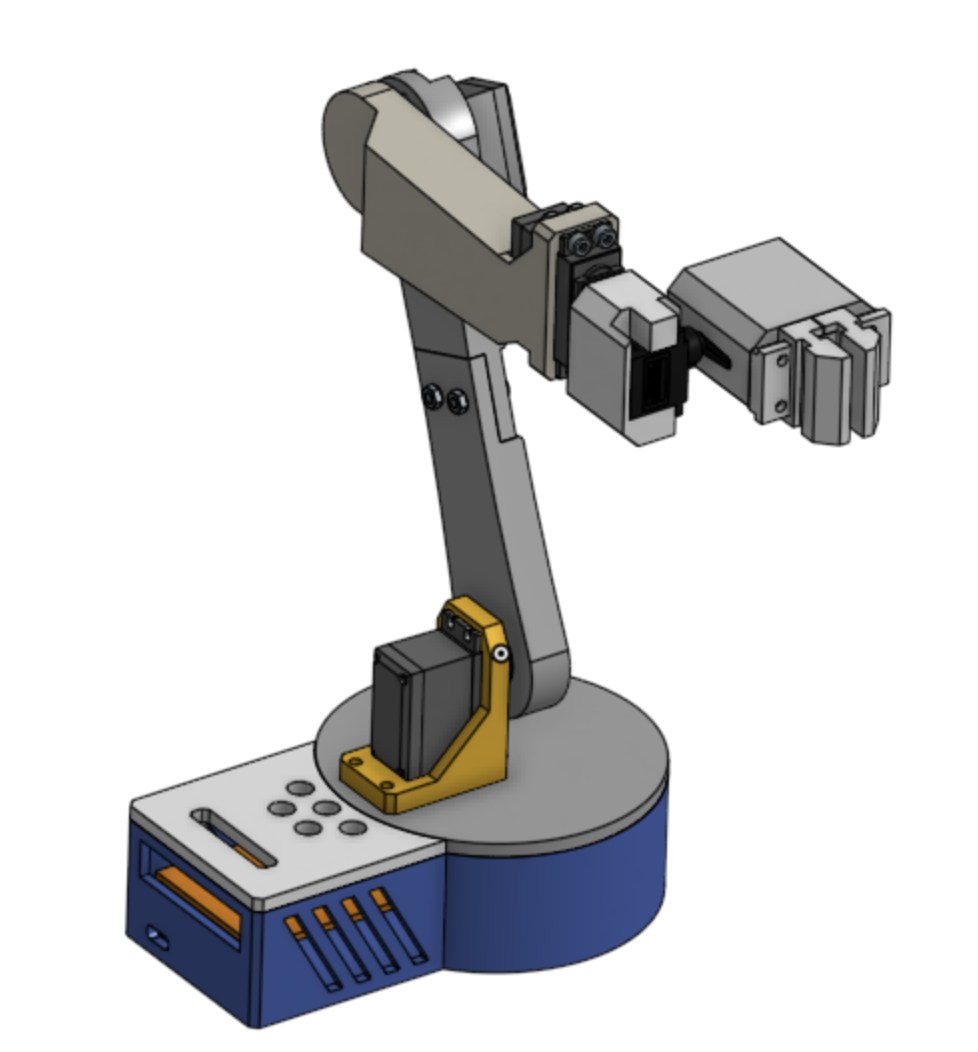
Overview
A 3D-printed articulated arm with five degrees of freedom, built in high school and finished in January 2025. The kinematic layout is a base yaw joint carrying a three-link planar arm — shoulder pitch, elbow pitch, and wrist pitch all rotate in the same vertical plane — plus a wrist roll axis and a parallel-jaw gripper. The shoulder pivot sits on the base yaw axis, so there is no horizontal offset to account for when solving position.
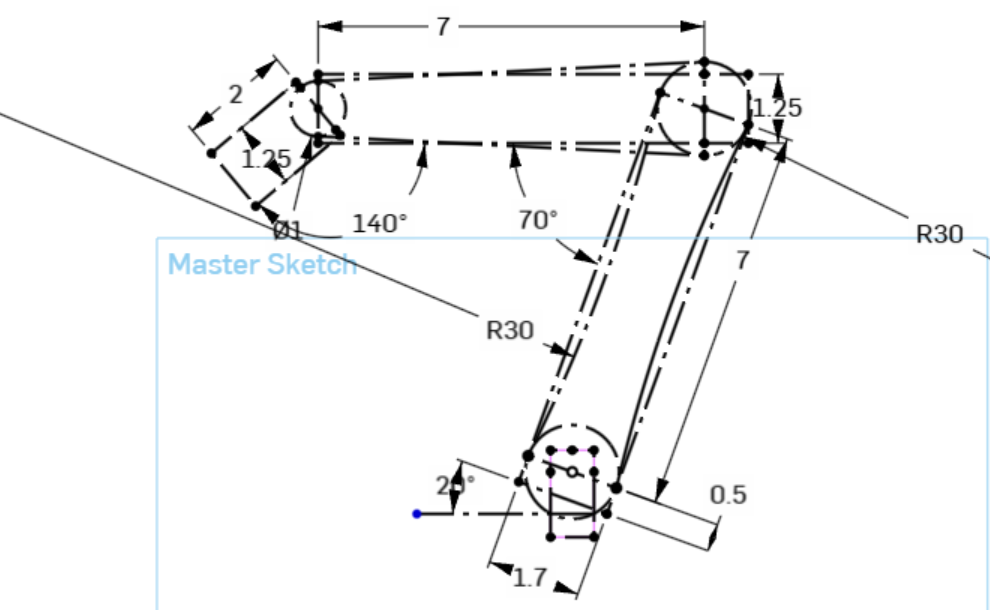
The master sketch drives the geometry: 7 in upper and lower links, a 140° span at the shoulder and 70° at the elbow. Four MG996 servos take the load-bearing joints, with two MG90s at the wrist and gripper, running off an ESP32 in C++ and a 5–6 V 8 A supply. FEA on the printed links checked they stayed rigid under load at full extension. Most parts bolt to standard servo horns; the fasteners are 14 M4 screws with nuts, 4 M2 screws, and a rubber band on the gripper.
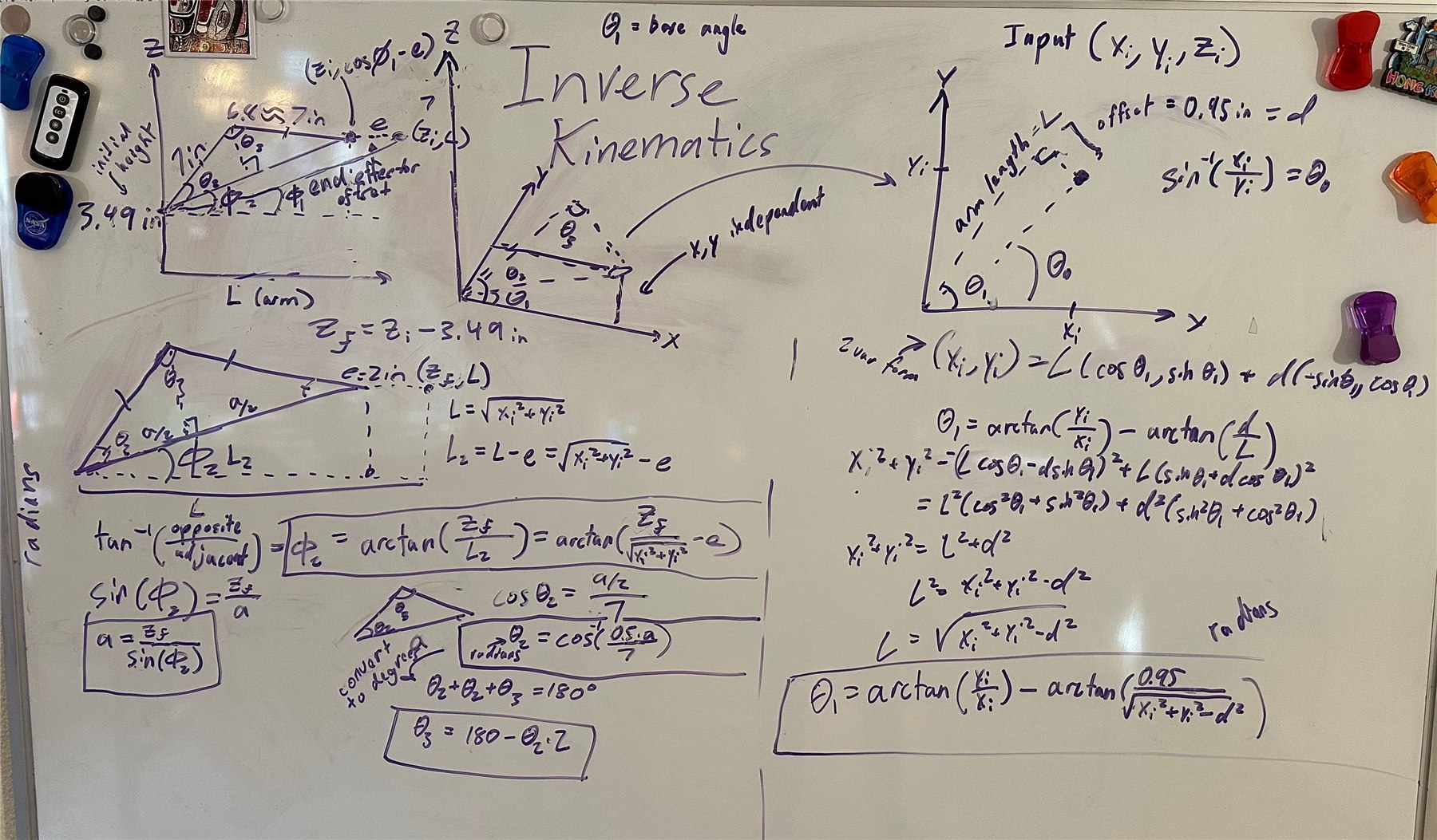
Working payload is around 100 g. The intended demonstration was picking up socks — the gripper never managed those, and settled for garlic. The original control code was lost when I migrated the machine to Linux, so what remains is the inverse kinematics derivation below, which is enough to reconstruct it.
Design notes
- 5 DOF across 6 servos: base yaw, shoulder pitch, elbow pitch, wrist pitch, wrist roll, gripper
- Base yaw plus a 3R planar arm, with the shoulder pivot on the yaw axis
- 7 in upper and lower links; 140° shoulder span, 70° elbow span
- 4× MG996 at the load-bearing joints, 2× MG90s at wrist and gripper
- ESP32 running C++, 5–6 V 8 A supply
- 3D-printed linkages and parallel-jaw gripper, assembled with M4 and M2 hardware
- FEA on the printed links to verify rigidity under load
- Working payload around 100 g
- Analytical inverse kinematics derived by hand; CAD published on Onshape